An unexpected result! Discovery
of X-rays in 1895.
(Illustration by Alejandro
Martínez de Andrés, CSIC 2014)
An unexpected result! Discovery
of X-rays in 1895.
(Illustration by Alejandro
Martínez de Andrés, CSIC 2014)
By the end of the 19th century, in
1895, Wilhelm
Conrad Röntgen (1845-1923),
a German scientist from the University of Würzburg, discovered
a form of
radiation (of unknown nature at that time, and hence the name X-rays)
which had the property of penetrating opaque bodies. In the first
paragraph of his communication
sent to the Society of Physics and Medicine of Wurzburg (1895)
he reports the discovery as follows:
After producing an
electrical
discharge with a Ruhmkorff’s
coil through a Hittorf’s
vacuum tube, or a sufficiently evacuated Lenard,
Crookes
or similar
apparatus, covered with a fairly tight-fitting jacket made of thin,
black paperboard, one sees that a cardboard sheet coated with a layer
of
platinum and barium cyanide, located in the vicinity of the apparatus,
lights up brightly in the completely darkened room regardless of
whether the coated side is pointing or not to the tube. This
fluorescence occurs up to 2 meters away from the apparatus. One can
easily be convinced that the cause of the fluorescence proceeds from
the discharge apparatus and not from any other source of the line.
To learn about
some aspects of
the discovery, as well as
about personal aspects of Röntgen, see also
the chapter
dedicated
to some biographical
outlines. But if you can read Spanish, there is an
extensive chapter dedicated to both the historical
details around Röntgen and his discovery.


- Left: Wilhelm
Conrad
Röntgen (1845-1923), around 1895 with
an X-ray photograph of his wife's hand showing her
wedding ring . For his discovery
Röntgen won the Nobel Prize in
Physics in 1901.
- Right: Typical
hospital radiology equipment
X-rays are invisible to our eyes but they can produce visible images if
we use photographic plates or special detectors...

 Left: Radiographic
image of a hand
Right: Radiographic
image of a monkey
Left: Radiographic
image of a hand
Right: Radiographic
image of a monkey
 Left: Radiographic
image of a well-done weld
Right: Poorly-done
weld (black line)
Left: Radiographic
image of a well-done weld
Right: Poorly-done
weld (black line)

A painting and its X-ray photograph
showing two superimposed paintings on the same canvas
(Charles II of Spain, by
Carreño de Miranda, Museo del Prado, Madrid)
Many
years
passed from the discovery of X-rays in 1895 until that finding
produced a revolution in the fields of Physics, Chemistry and Biology.
The potential applications in these areas came in 1912
indirectly from
the
hand of Max von Laue (1879-1960),
professor at the Universities of Munich, Zurich,
Frankfurt, Würzburg and finally Berlin.
Paul Peter Ewald
(1888-1985) encouraged
his friend, Max Laue, to become interested in his own experiments on
interference between long-wavelength radiation (practically visible
light) in a "crystalline" model based on resonators (it is worth noting
that the wave-particle duality was also being debated at that time).
Laue then had the idea that the much shorter electromagnetic rays,
which X-rays were supposed to be, would cause some kind of diffraction
or interference phenomenon in a medium, and that a crystal could
provide this medium. So, in 1912, induced by the ideas of his friend
Ewald, and intending to demonstrate the wave nature of this new
radiation, Max Laue placed crystals of copper sulfate and blende in
front of the X-rays, obtaining confirmation of his hypothesis and at
the same time demonstrating the periodic nature of crystals through
diffraction. For these findings Max von Laue received the Nobel
Prize in Physics in 1914
However,
those who really benefited from the discovery of the Germans were the
British Braggs (father and son), William
H. Bragg (1862-1942)
and William
L. Bragg (1890-1971),
who together in 1915 received the Nobel Prize in Physics for
demonstrating the
usefulness of the phenomenon discovered by von Laue for
obtaining the
internal structure of crystals - but all this will be the subject of
later chapters. This
chapter will deal
exclusively with the nature and production of
X-rays in the context of crystallography.
X-rays
are electromagnetic radiations, of the same nature as visible
light, ultraviolet or infrared radiations, and the only thing that
distinguishes them from other electromagnetic radiations is their
wavelength, which is about 10-10 m (equivalent
to the unit of length known as one Angstrom).
Graphic
representation of an electromagnetic wave, showing its associated
electric (E)
and magnetic (H)
fields, moving forwards at the speed of light.
The
continuous spectrum of visible light (wavelength decreases
from red to violet )
Excellent information on
the electromagnetic spectrum can be
found in some pages offered by NASA.
The reader can also learn
about X-rays
and their applications in Medical
Radiography.
ν(Hz)
λ(m) = 3 108 m Hz
E(J)
= h(J/Hz) ν(Hz) = k(J/K molecule) T(K)
h
= 6.6 10-34 (J/Hz);
k = 1.4 10-23 (J/K
molecule); 1 eV = 1.6 10-19
(J)
Figure
taken from the Berkeley
Lab
The most interesting
X-rays for Crystallography are those having a
wavelength close to 1 Angstrom (the hard
X-rays in
the diagram above), which is a distance very close to the interatomic
distances occurring in molecules and crystals. These type of X-rays
have
a frequency of approximately
3
million THz (tera-hertz) and to an energy of 12.4 keV
(kilo-electron-volts), which in turn would correspond to a
temperature of about 144 million degrees Celsius. These
wavelengths are
produced in Crystallography laboratories and in large
synchrotrons as ESRF, ALBA,
Diamond, DESY,
...
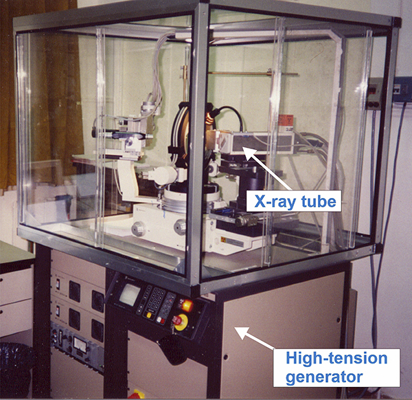
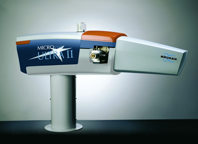
X-ray generator in
a Crystallography laboratory. The
goniometric and detection systems are shown behind the X-ray tube.

Aerial
photograph of the synchrotron at the ESRF in
Grenoble (France). Note its circular geometry
The
equipment used in crystallographic laboratories to
produce X-rays is relatively simple. They
have a high
voltage generator (50,000 volts) that brings high voltage to the
so-called X-ray tube, where the radiation is actually
produced. You could
also take a look at the
web page "The Cathode Ray Tube site".
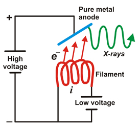
Those 50 kV are supplied as a potential difference (high voltage)
between an incandescent filament (through which a low voltage
electrical current of intensity i
passes: around 5 A at 12 V) and a
pure metal (usually copper or molybdenum). This produces an
electrical current (of free electrons) between them of about 30 mA.
From the incandescent filament (negatively charged) the free electrons
jump to the anode (positively charged) causing (in the pure metal) a
reorganization in its electronic energy levels. Have a look to this
video produced by Bruker and showing the different
technologies used to produce X-rays for single-crystal diffraction.
This
is a process that generates a lot of heat, so that X-ray tubes
must be very well chilled. An alternative to conventional X-ray tubes
are the rotating
anode generators,
in which the anode in the form of a cylinder is maintained in a
continuous rotation, so that the incidence of electrons is distributed
over its cylindrical surface and thus a higher power can be obtained.
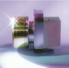
Left:
Rotating anode generator
Right: Rotating
anode of polished copper (images taken from Bruker-AXS)
The
so-called "characteristic X-rays" are
produced according to the following scheme:

a)
Energy state of electrons in an atom of the anode that is
going to be reached by an electron from the filament. b)
Energy state of the same electrons after impact with the electron from
the filament. The incident electron bounces and ejects an electron from
the anode, producing the corresponding hole. c)
An electron of a higher energy level falls and occupies the hole. This
energy jump, perfectly defined, generates the so-called characteristic
X-rays of the anodic material.

Left:
In an X-ray tube the electrons emitted
from the cathode are accelerated
towards the metal target anode by an accelerating voltage of typically
50 kV. The high energy electrons interact with the atoms in the metal
target. Sometimes the electron comes very close to a nucleus in the
target and is deviated by the electromagnetic interaction. In this
process, which is called bremsstrahlung (braking radiation), the
electron loses much energy and a photon (X-ray) is emitted. The energy
of the emitted photon can take any value up to a maximum corresponding
to the energy of the incident electron.
Right:
The high energy electron can also cause
an electron close to the
nucleus in a metal atom to be displaced. This vacancy
is filled by an electron further out from the nucleus. The well defined
difference in binding energy, characteristic of the material, is
emitted as a monoenergetic photon. When detected this X-ray photon
gives rise to a characteristic X-ray line in the energy
spectrum. Animations taken from Nobelprize.org.


Left: New
microfocus X-ray tube. Image taken from Incoatec
Right: New development for an of X-ray source
based on liquid metal anodes. Taken from Excillum.
There is
an animation showing this technology
The
energetic restoration of the
excited anodic electron is carried out
with an X-ray emission with a frequency that corresponds exactly to the
specific energy gap (quantum) that the electron needs to return to its
initial state. These X-rays therefore show a specific wavelength and
are known as characteristic
wavelengths of the anode. The most important
characteristic wavelengths in X-ray Crystallography are the so-called K-alpha
lines (Kα),
produced by the electrons falling to the innermost layer of the atom
(higher binding energy). However, in addition to these specific
wavelengths, a continuous range of wavelengths, very close to each
other, is also produced known as the continuous
radiation which is due to the braking of the
incident electrons when they hit the metal target.
Distribution of X-ray
wavelengths produced in a conventional X-ray tube where the
anode material is copper (Cu),
molybdenum (Mo),
chromium (Cr)
or tungsten (W).
Over the so-called continuous spectrum, the characteristic K-alpha (Kα) and
K-beta (Kβ)
lines are shown. The starting point of the continuous spectrum appears
at a wavelength which is approximately 12.4 / V, (Angstrom) where V
represents the
amount of kV between anode and filament. For a given voltage between
the anode and filament, only the characteristic wavelengths of
molybdenum are obtained (figure on the left).
In synchrotrons,
the generation of X-rays is quite different. A synchrotron facility
contains a large ring (on the order of kilometers), where electrons
move at a very high speed in straight channels that
occasionally
break to match the curvature of the ring. These electrons are made to
change direction to go from one channel to another using magnetic
fields of high energy. It is at this moment, when electrons change
their
direction, that the electrons emit a very high energy radiation
known as synchrotron
radiation. This radiation is composed of a continuum of
wavelengths ranging from microwaves
to the so-called hard
X-rays.
Synchrotrons
appearance is very similar to that shown in the following schemes:
A
synchrotron scheme. The linear accelerator (Linac) and the circular
accelerator (Booster) are seen in the center, surrounded by the outer
storage ring. The emitted X-rays are directed to the beamlines.


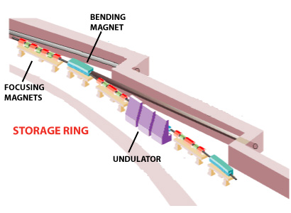
Left:
General sketch of a synchrotron. The
central circle is where the charged particles are accelerated (linac
& booster). The outer circle is the storage ring, formed by
crooked lines, at the end of which the experimental stations are
installed.
Right: Outline of the junction of two crooked
lines of the storage ring of a synchrotron. X-rays appear due
to the change of direction of the charged particles.

Scheme of operation of a synchrotron, taken from synchrotronmovies.com
This
animation represents a synchrotron facility containing 12 sectors, six
of which being hard X-ray ID beamlines (blue radiation, small
periodicity magnet arrays) and the other six soft X-ray beamlines (red
radiation, large periodicity magnet arrays). In addition, there are 12
bending-magnet arcs (golden radiation).
Outline of the point between two
straight segments in the storage ring of a synchrotron. Image taken
from the ESRF
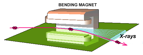 Details of how X-rays are produced in a
synchrotron in the curvature of the electrons' trajectory
inside the storage ring. Image taken from the ESRF
Details of how X-rays are produced in a
synchrotron in the curvature of the electrons' trajectory
inside the storage ring. Image taken from the ESRF
The
X-rays obtained in the synchrotrons have two clear advantages
for crystallography:
- the wavelengths can be tuned at will, and
- its brilliance is at least 1021
times higher that those obtained with a conventional X-ray tube (see
the image below).
Here can you find a list
of synchrotrons and storage rings used as synchrotron radiation sources,
and free electron lasers around the world.

The following image shows an
outline of an
experimental station of a synchrotron: a) the optics hutch, where
X-rays are filtered and focused using curved mirrors and
monochromators; b) the experimental hutch, where the goniometer, sample
and detector are located and where the diffraction experiment is done
and, c) the control cabin, where the experiment is monitored
and,
if required, also evaluated.
Outline
of an experimental station in a
synchrotron
Lightsources.org
contains news and science
highlights from each light source facility, as well as photos and
videos, education and outreach resources, a calendar of conferences and
events, and information on funding opportunities.
The
radiation used for crystallography is usually monochromatic
(or nearly monochromatic), that is, a radiation with exclusively (or
almost exclusively) a single wavelength. In order to achieve
this, the so-called monochromators
are used, which consist of a system of crystals that, based on Bragg's
Law (which will be presented in another chapter),
are able to "filter" (through the interaction between the crystals and
the X-rays) the polychromatic radiation, allowing only
one wavelength (color), as shown below.
Outline
of a monochromator.
Polychromatic
radiation (white) coming from the left (below) is "reflected" , in
accordance with Bragg's
Law,
(to be seen in subsequent chapter), in different orientations of the
crystal to produce ("to filter") a monochromatic radiation that is
reflected again ("filtered") in the secondary crystal. For the
moment
it is enough that the reader is aware that this law will allow us to
understand how the crystals "reflect" the X-rays, behaving as
special mirrors . Image
taken
from the ESRF.
X-rays
interact with the electrons of matter... A monochromatic
beam (ie with a single wavelength) suffers an exceptional
attenuation,
proportional to the thickness being crossed. This attenuation may
arise from several factors: a)
the body heats up, b)
a fluorescent
radiation, with different wavelength, is produced
&
accompanied by photoelectrons, both being characteristic of the
material (this leads to the photo-electron spectroscopies, Auger
and PES);
and c) scattered
X-rays with the same wavelength (coherent and
Bragg)
or with slightly higher wavelengths (Compton),
together with the scattered electrons.
Of all these effects, the most
important one is fluorescence,
where the absorption increases by increasing incident wavelength.
However, this behavior has discontinuities (anomalous
dispersion)
for those energies that correspond to electronic transitions between
different energy levels of the material (this leads to the EXAFS
spectroscopy).
Spectrum emitted by a metallic anode
showing its characteristic wavelengths (continuous line). In the same figure, but referred to a
vertical axis of absorbance
(not drawn) the increasing and discontinuous variation of the
absorption (dashed line) of a given material is also shown.
This gives an idea of the use of this property as a
filter to
obtain monochromatic radiation, at least separating the double Kα1 - Kα2
from
the rest of the spectrum. This approach, using concrete materials
with specific absorption
capacities, was used in Crystallography
laboratories until the early 1970's to obtain
monochromatic
radiation.
Special
mention deserves the recent
discovery introduced in the field of femtosecond X-ray protein
nanocrystallography. Using this technique (XFEL: X-ray Free Electron Laser),
based on the use of X-rays
obtained from a free electron laser, "snapshots" of X-ray
diffraction can be obtained in the femtoseconds scale. It has been
proposed that femtosecond X-ray pulses can be used to outrun even the
fastest damage processes by using single pulses so brief that they
terminate before the manifestation of damage to the sample in less time
than it needed to be damaged by the crystallites radiation.This will
imply a giant step to remove virtually all the difficulties in the
crystallization process, especially for proteins (see
these articles: Nature (2011) 470, 73-77, Nature
(2013) and Nature(2014)).
In this sense, it is also worth
quoting the article published in Radiation
Physics and Chemistry (2004) 71, 905-916, which already
warned on the future importance of the free electron laser on
structural biology.
 The
European XFEL generates
ultrashort X-ray flashes, 27,000 times per second
and with a brilliance that is a billion times higher than that of the
best conventional X-ray radiation sources. Thanks to its outstanding
characteristics, which are unique worldwide, the facility opens up
completely new research opportunities for scientists and industrial
users. It could be interesting to
look at the video offered on the web site
of the international consortium,
or directly
through this link.
The
European XFEL generates
ultrashort X-ray flashes, 27,000 times per second
and with a brilliance that is a billion times higher than that of the
best conventional X-ray radiation sources. Thanks to its outstanding
characteristics, which are unique worldwide, the facility opens up
completely new research opportunities for scientists and industrial
users. It could be interesting to
look at the video offered on the web site
of the international consortium,
or directly
through this link.
Regarding the use of these powerful X-ray sources for determining the
structure of biological macromolecules, the interested readers should
consider the very promising results published in Nature (2016)
530, 202-206.
This study provides the opportunity to use not only the information
contained in the diffraction spots generated by crystals, but
also in the very weak intensity distribution found around and between the diffraction
spots, the so called continuous diffraction.
With X-rays from free-electron lasers crystallographic
applications are
extended to nanocrystals, and even to single non-crystalline biological
objects and even movies
of biomolecules in action can be produced.
To generate
the X-ray
flashes, bunches of electrons will first be accelerated to high
energies and then directed through special arrangements of magnets
(undulators). In the process, the particles will emit radiation that is
increasingly amplified until an extremely short and intense X-ray flash
is finally created.
Recently, the modification that involves replacing the so-called
material undulators (magnets) with a new optical device also based on
laser technology, dramatically reduces the size of the XFEL by about
10,000 times and the size of the accelerator by 100 times, leading to
an incredible reduction in size and price of the so called CXFEL
(compact X-ray free-electron laser).
Advanced readers should also read the chapter especifically dedicated
to the so called the revolution of XFELs.
In any case, X-rays,
like any light "illuminate" and "let to see", but in a different manner
than we see with our eyes. We encourage you to go forward, to
understand how X-rays allow us "to see" inside crystals, that
is, to "see" the atoms and the molecules.
Next chapter:
The
symmetry of crystals
Table of contents